Monday, September 21, 2020

DHCP-Snooping Configuration with Aruba Switch Series 2930, 2530.


DHCP-Snooping Configuration with Aruba Switch Series 2930, 2530.

DHCP Snooping is a Layer 2 security switch feature which blocks unauthorized (rogue) DHCP servers from distributing IP addresses to DHCP clients also call option 82 of this service.

This lab configuration with Aruba Switch Series 8320, 2930.

We need trusted DHCP server IP address to configure DHCP-snooping on your network.


DHCP Starvation attack is a common network attack that targets network DHCP servers. Its primary objective is to flood the organization’s DHCP server with DHCP REQUEST messages using spoofed source MAC addresses. The DHCP server will respond to all requests, not knowing this is a DHCP Starvation attack, and assign available IP addresses until its DHCP pool is depleted.

At this point the attacker has rendered the organization’s DHCP server useless and can now enable his own rogue DHCP server to serve network clients. DHCP Starvation is often accompanied by a Man-in-the-Middle attack as the rogue DHCP server distributes fake IP address parameters, including Gateway & DNS IP address, so that all client traffic passes through the attacker for inspection.

Typical Man-in-the-Middle attack. Client data streams flow through the attacker

Using packet capture and protocol analysis tools the attacker is able to fully reconstruct any data stream captured and export files from it. In fact the process so simple it only requires a basic level of understanding of these type of network tools.

In other cases the Man-in-the-Middle attack can be used as a reconnaissance attack with the objective to obtain information about the network infrastructure, services but also identify hosts of high interest such as financial or database servers.

It should be by now evident how a simple attack can become a major security threat for any organization. The above attacks are examples on how easy hackers can infiltrate the network and get access to valuable information by simply connecting an unauthorized/untrusted device to an available network port effectively bypassing firewalls and other levels of security.


ROGUE DHCP SERVERS – A MAJOR SECURITY THREAT & SOURCE OF NETWORK DISRUPTIONS

Rogue DHCP servers are a common problem within enterprise organizations and are not always directly related with an attack. Rogue DHCP Servers tend to appear out of nowhere thanks to users who connect consumer-grade network devices to the network infrastructure unaware that they have connected an unauthorized device with a rogue DHCP server enabled.

The Rogue DHCP server then begins assigning IP addresses to hosts within the network therefore causing network connectivity problems and in many cases – major service disruptions. In a best case scenario DHCP clients are served with an invalid IP address disconnecting them from the rest of the network. Worst case scenario would be the clients been assigned an IP address used by network infrastructure devices e.g the VLAN interface on the Core switch or a firewall interface, causing serious network disruptions and conflicts.

A rogue DHCP server in action, taking control of DHCP services

While many organizations enforce security policies that do not allow 3rd party or unauthorized devices to be connected to their network, there are still incidents where users who do not understand (or care about) the security implications continue to connect these devices to the network infrastructure without consulting their IT Department.

Educating users and enforcing security policies can be extremely challenging which is why security mechanisms need to be in place to help mitigate these incidents and is where DHCP Snooping comes into the picture.

DHCP SNOOPING SUPPORT FOR Aruba 2930M, 2930F, 2530M, 2530F etc.

DHCP Snooping is available for above switch series like 2930M, 2930F, 2530M, 2530F.

DHCP Snooping is considered a standard security feature and does not require any additional licensing for the older switch series and new IOS operating systems, therefore the feature is available and readily configurable on all switches.

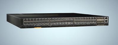
Examples of  Aruba switch series like 2930M, 2930F, 2530M, 2530F

DHCP Snooping can be enabled globally and on a per-VLAN basis. This means you can enable it for all VLANs (globally) or only for specific including VLAN ranges e.g VLANs 1-20 & VLANs 45-50.

HOW DHCP SNOOPING WORKS – DHCP SNOOPING CONCEPTS – TRUSTED, UNTRUSTED PORTS/INTERFACES

DHCP Snooping is a Layer 2 security switch feature which blocks unauthorized (rogue) DHCP servers from distributing IP addresses to DHCP clients. In fact Cisco was the first vendor to implement DHCP Snooping as a security feature in its network switches and other vendors have since then followed with similar features.

Note-It is important to note that DHCP snooping is an access layer protection service. It does not belong in the core network.

The way DHCP Snooping works is fairly straight forward. DHCP Snooping categorizes all switch ports into two simple categories:

·         Trusted Ports

·         Untrusted Ports

Trusted Port, also known as a Trusted Source or Trusted Interface, is a port or source whose DHCP server messages are trusted because it is under the organization’s administrative control. For example, the port to which your organization’s DHCP server connects to consider a Trusted Port. This is also shown in the diagram below:


DHCP Snooping Concepts: Trusted and Untrusted Ports

An Untrusted Port, also known as an Untrusted Source or Untrusted Interface, is a port from which DHCP server messages are not trusted. An example on an untrusted port is one where hosts or PCs connect to from which DHCP OFFER, DHCP ACK or DHCPNAK messages should never be seen as these are sent only by DHCP Servers.

How to configure DHCP-Snooping in Aruba Switch?

Answer- We have to configure DHCP-snooping to avoid unauthorized (rogue) DHCP servers offering IP addresses to DHCP clients.

Kindly find the below configuration: -

Step1: Aruba-tech-(config)#dhcp-snooping authorized-server 10.20.62.11 # for Trusted DHCP Server.

Step2: Aruba-tech-(config)#dhcp-snooping trust (trunk port)         #Uplink port will be trust port other will be untrust.

Step3: Aruba-tech-(config)#dhcp-snooping vlan _____         #All vlan should be call in this cmd.

Step4: Aruba-tech-(config)#dhcp-snooping                #for enable DHCP-Snooping.


Saturday, September 5, 2020

Peer Keep alive Lab Configuration with Aruba CX Switch Series 8320

Peer Keep alive Lab Configuration with Aruba CX Switch Series 8320

This lab configuration with Aruba Switch Series 8320, 2930.


Distribution uses UDP-based peer keep alive message to determine if any link goes down at this level or the peer has completely failed. The following opening rules must be followed to use peer keep alive links.

1.      An IP address must be configure for a peer keep alive VLAN interface and the same IP address must be configured as a peer keep alive distribution on the peer distribution switch.


2.      There must be logical layer 3 connectivity between the two IP address configured for the peer keep alive VLAN interface.


3.      STP cannot run on a peer-keep alive links.


4.      A keep alive VLAN can only have one member port.


5.      The default VLAN can’t configure for a peer keep alive. It will show an error message.

Considering the below facts:

  1. Configuration of the KA will be done on the Default VRF.
  2. The IP address on Primary and Secondary are respectively 10.x.x.x and 10.x.x.y
  3. The Loopback interface ID is 0.( Also can use physical interface)
  4. The correct dedicated VLAN assignment of the interfaces are done.


Here are the steps/commands (only highlighted portion) to configure the KL.


  1. Step 1: Creating a Loopback interface on both the VSX member switches.


On the Primary:

============

Create a Loop Back Interface if you do not have one.

interface loopback 0

ip address 10.x.x.x/32

            On the Secondary:

============

Create a Loop Back Interface if you do not have one.

interface loopback 0

ip address 10.x.x.y/32


  1. Step 2: Confirm the above IPs are reachable through the newly configured interfaces.

a.       Confirm with the ICMP test if the IP is reachable

b.      Check with ‘show arp’ to see which interface the IP addresses are learnt (it should be learnt on the newly commissioned link)


  1. Step 3: Create the KeepAlive Link for the VSX pair switches.


On the Primary:

============

vsx

    inter-switch-link lag XXX

    role primary

    keepalive peer 10.x.x.y source 10.x.x.x


On the Secondary:

============

vsx

    inter-switch-link lag XXX

    role secondary

    keepalive peer 10.x.x.x source 10.x.x.y


  1. Step 4: Check the KA link is established and working. (Troubleshooting step)


a. show vsx status keepalive (KA state should be like this ‘Keepalive State: Keepalive-Established’)

b. show vsx configuration keepalive


Wednesday, August 5, 2020

Aruba Switch Series 2930 AAA (Authentication Authorization and Accounting)

Aruba Switch Series 2930 AAA (Authentication Authorization and Accounting)

AAA is authentication management protocol


AAA network security services provide the primary framework through which a network administrator can set-up access control on network points of entry or network access servers.

  • Port No-49 TACACS uses TCP services to delivery data.
  • RADIUS uses Port No-1812 for authentication and authorization and Port No-1813 for accounting.
  • All the AAA packets are encrypted but RADIUS Only the password are encrypted while the other information such as username, accounting information etc are not encrypted.

1) Authentication identifies a user.

2) Authorization determines that what user can do on the network.

3) Accounting monitors the network usage time for billing purposes.

AAA information is typically stored in an external database or remote server such as a RADIUS or TACACS+ server. The information can also be stored locally on the access server or router.

Remote security servers, such as RADIUS and TACACS+ servers, assign users specific privileges by associating attribute-value pairs, which define the access rights with the appropriate user. All authorization methods must be defined through AAA.

What is RADIUS Protocol

The RADIUS (Remote Authentication Dial-In User Service) protocol carries authentication, authorization, and configuration information between a network access server (NAS) and a RADIUS authentication server.

Authentication with RADIUS allows for a unique password for each user, instead of the need to maintain and distribute switch-specific passwords to all users. RADIUS verifies identity for the following types of primary password access to the switch:

1)      Serial port (console)

2)      Telnet

3)      SSH

4)      SFTP/SCP

5)      Web Agent

6)      Port-Access (802.1X)

Aruba-OS switches support RADIUS accounting for web-based authentication and MAC authentication sessions, collecting resource consumption data and forwarding it to the RADIUS server. This data can be used for trend analysis, capacity planning, billing, auditing, and cost analysis.

Requests and responses carried by the RADIUS protocol are called RADIUS attributes. These attributes provide the information needed by a RADIUS server to authenticate users and to establish authorized network service for them. The RADIUS protocol also carries accounting information between a network access server and a RADIUS accounting server.

RADIUS is a client/server protocol. The RADIUS client is typically a network access server. The client passes user information to designated RADIUS servers and acts on the response that is returned. RADIUS servers receive user connection requests, authenticate the user, and then return the configuration information necessary for the client to deliver service to the user.

What is TACACS+ Protocol

TACACS AAA systems are used as a single point of management to configuring and store user accounts. They are often coupled with directories and management repositories, simplifying the set up and maintenance of the end-user accounts.

In the authorization function of the AAA system, network devices with Authentication Services can provide fine-grained control over user capabilities for the duration of the user’s session; for example, setting access control or session duration.

Enforcement of restrictions to a user account can limit available commands and levels of access.

TACACS+ authentication provides a central server in which you can allow or deny access to switches and other TACACS-aware devices in your network. TACACS employs a central database that creates multiple unique user name and password sets with their associated privilege levels. This central database can be accessed by individuals via the Aruba-OS switch from either a console port or via Telnet.

TACACS+ uses an authentication hierarchy consisting of:

Remote passwords assigned in a TACACS+ server

Local passwords configured on the switch


v  In the event of a connection failure, a TACACS+ server defaults to locally assigned passwords for authentication control.

Saturday, July 25, 2020

Aruba Switch 2930 Series NTP (Network Time Protocol) Configuration


Aruba Switch NTP (Network Time Protocol) Configuration


NTP (Network Time Protocol) is time management protocol.


NTP (Network Time Protocol) for network time managing we use this in our organization because 100- 1000 devices are running in a network then it’s very difficult to manage time on all devices that’s why we use this mechanism. It uses port no 123 for transport and use UDP services for polling time from server to the devices.

NTP uses operate different modes. Supports four different modes.
1-Client
2-Server
3-Peer
4-Broadcast/multicast.

NTP (Network Time Protocol) operating modes define the NTP communication between NTP devices. NTP communication between two different devices includes NTP Time requests and NTP control queries. NTP Time request communication is the request from an NTP client for time synchronization from an NTP server. NTP Control queries are the communication messages for configuration information.

Following are the important NTP operating modes:
1-Client: An NTP client is a network device which is configured to let its clock synchronized from an external NTP Time Server. NTP Client mode devices will not provide synchronization services to other network infrastructure devices.

2-Server: An NTP server is a network device which is running NTP service and configured to provide Time information to NTP clients using NTP. NTP servers provide only Time information to NTP Clients and will never accept time synchronization information from other devices.

3-Peer: NTP peers does not have authority over the other. NTP peer mode, each device can provide time synchronization to the other.

4-Broadcast/multicast: In Broadcast/multicast mode, the NTP server broadcasts/multicasts the time synchronization information to all NTP clients.

In this mode you can run only troubleshooting command but cannot run modification command if you want to change in switch. Need to go first in configure mode then can execute modification command.
Aruba-tech#  
Aruba-tech# configure

This command is use for NTP tries to adjust the clock in small steps and will continue until the client gets the accurate time.
Aruba-tech(config)#timesync ntp

This command use for sending synchronization packet to only NTP configured device with the server address.
Aruba-tech(config)#ntp unicast

We define NTP server by giving IP address of NTP server.
Aruba-tech(config)#ntp server 10.12.1.25 iburst

also need to adjust time according to location.
Aruba-tech(config)#time timezone 330

After confirgured complete NTP configuration then need to enable NTP for this device. We will have to give this command.
Aruba-tech(config)#ntp enable

timesync ntp
ntp unicast
ntp server 10.12.1.25 iburst
ntp enable
time timezone 330


Aruba-tech# show  ntp associations detail
Aruba-tech# show  ntp associations
Aruba-tech# show  ntp authentication
Aruba-tech# show  ntp servers
Aruba-tech# show  ntp
Aruba-tech# show  ntp status

This is configuration for NTP of Aruba switch. This switch has lots of excellence feature. I will update all feature which require in our network.

Friday, July 10, 2020

Aruba Switch 2930F 48G Poe Basic Configuration


Aruba Switch 2930F 48G Poe Basic Configuration


First You need a console cable to configure a switch. Console is an interface. Via this interface we can execute any command.
 
 
After connect this cable with switch to laptop. Need to open console (Putty).

 
You can download from this link https://www.chiark.greenend.org.uk/~sgtatham/putty/latest.html

When will get console of fresh switch. you will get with this little default configuration

; JL256A Configuration Editor; Created on release #WC.16.07.0005
; Ver #14:21.4f.f8.1d.9b.3f.bf.bb.ef.7c.59.fc.6b.fb.9f.fc.ff.ff.37.ef:22
hostname "Aruba 2930f"
module 1 type jl256a
vlan 1
   name "DEFAULT_VLAN"
   no untagged 1-48
   untagged 49-50,Trk1
   no ip address
   ipv6 address dhcp full
   exit


Now you need to configure fresh switch according to your requirement.

In this mode you can run only troubleshooting command but cannot run modification command if you want to change in switch. Need to go first in configure mode then can execute modification command.
Aruba-tech#  
Aruba-tech# configure

If you want to change switch name you can run this command.
Aruba-tech(config)#hostname "Aruba-tech"    
              
If you want that if you are doing anything on switch. If you stop doing anything on switch it will automatic disconnect console.
Aruba-tech(config)#console idle-timeout 120
Aruba-tech(config)#console idle-timeout serial-usb 120

If you want to run multiple VLAN on this switch you need to configure trunk port so that different VLAN user data go through via this link.
Aruba-tech(config)#trunk 1/51

For Security  purpose you need to configure password.
Aruba-tech(config)#include-credentials
Aruba-tech(config)#password manager user-name "administrator” Password 123@ccie

If you need provide internet connectivity. You have to configure default-gateway it’s must be correct.
Aruba-tech(config)#ip default-gateway 10.20.100.1

For config SSH you need to run this command
Aruba-tech(config)#ip ssh timeout 60

If you need to give description on interface you run this command.
Aruba-tech(config-int)#interface 1/51
Aruba-tech(config-int)#name "CONNECTIVITY_TO_DIST_SW_PRI_PORT_1/1/16"
Aruba-tech(config-int)#exit

For VALN configure you have to run this command and this is very essential.
Aruba-tech(config)#vlan 1100
Aruba-tech(config-vlan)#name "Network_Management"
Aruba-tech(config-vlan)#tagged Trk1
Aruba-tech(config-vlan)#ip address 10.20.100.63 255.255.255.0
Aruba-tech(config-vlan)#exit

If you run manual STP you can run these command.
Aruba-tech(config)#spanning-tree Trk1 priority 4
Aruba-tech(config)#spanning-tree config-name "Aruba-tech"
Aruba-tech(config)#spanning-tree config-revision 1
Aruba-tech(config)#spanning-tree instance 1 vlan 1100-1116

This is basic configuration of Aruba switch.This switch has lots of excellence feature. I will update all feature which require in our network.